Debugging Boundary Optimization in Gate-Level Simulation
HEIDI ZHENG
Manager at NanDigits, Functional Netlist ECO, Functional Safety Fault Verification
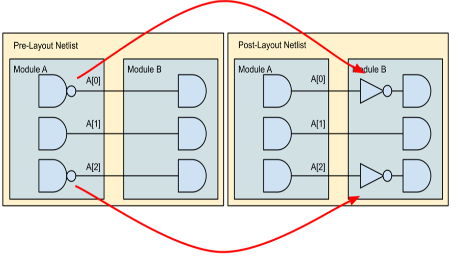
During the Place & Route (P&R) stage, backend tools may alter the phase of a port. This can result in a bus port having the same name in the post-layout netlist as in the pre-layout netlist, but with one or more bits inverted due to inverters being moved across hierarchy boundaries (boundary optimization). Figure 1 illustrates this scenario, where bus port 'A' in module 'Sub Module' has bits 0 and 2 inverted, and the parent module has inverters inserted in the fanouts of these bits.
This boundary optimization can create discrepancies in gate-level simulations using the post-layout netlist. A testbench polling the port 'A' may observe different values in gate-level simulation compared to RTL simulation. Therefore, it's crucial to compare the port phase in the post-layout netlist against the pre-layout netlist to adjust the gate-level read values accordingly.
This post describes a method to identify if a port's phase has changed during the P&R stage.
Solution
GOF supports Logic Equivalence Checking (LEC) on individual nets or buses. By loading the pre-layout netlist as a reference, GOF can easily determine if a net is equivalent, non-equivalent, or inverted compared to the reference net. The pre-layout netlist, which preserves the logic boundaries as in the RTL design, serves as the ideal reference.
Detailed Procedure
The following steps outline how to use GOF to detect phase changes:
# GOF Debug script: boundary_opti_debug.pl
use strict;

read_library("/proj/lib/tsmc40nm.lib"); # Read standard library
read_design("-imp", "post_layout.gv");  # Read post-layout netlist (implementation)
read_design("-ref", "pre_layout.gv");  # Read pre-layout netlist (reference)

set_top("dit_mod");  # Set module scope
compare("data_out");  # Check bus port 'data_out' phase

set_top("dot_mod");  # Set another module scope
compare("ctrl_state");  # Check bus port 'ctrl_state' phase
2. Execute the Script: Run the script using the command:
gof -run boundary_opti_debug.pl
3. Analyze the Output:
The output will indicate whether any bit of the bus has been inverted or is non-equivalent.
# Check Logic Equivalence of data_out in module dit_mod u_core/u_dit_top/u_dit_mod/data_out[0] is inverted in REF and IMP u_core/u_dit_top/u_dit_mod/data_out[1] is equal in REF and IMP u_core/u_dit_top/u_dit_mod/data_out[2] is equal in REF and IMP u_core/u_dit_top/u_dit_mod/data_out[3] is equal in REF and IMP u_core/u_dit_top/u_dit_mod/data_out[4] is equal in REF and IMP u_core/u_dit_top/u_dit_mod/data_out[5] is equal in REF and IMP
Total equal: 5 inv: 1 non-equal: 0
# Check Logic Equivalence of ctrl_state in module dot_mod u_core/u_dit_top/u_dit_mod/ctrl_state[0] is equal in REF and IMP u_core/u_dit_top/u_dit_mod/ctrl_state[1] is equal in REF and IMP u_core/u_dit_top/u_dit_mod/ctrl_state[2] is equal in REF and IMP u_core/u_dit_top/u_dit_mod/ctrl_state[3] is equal in REF and IMP
Total equal: 4 inv: 0 non-equal: 0
Conclusion
This method provides a straightforward way to identify and debug boundary optimization issues during the P&R stage, ensuring consistency between RTL and gate-level simulations.