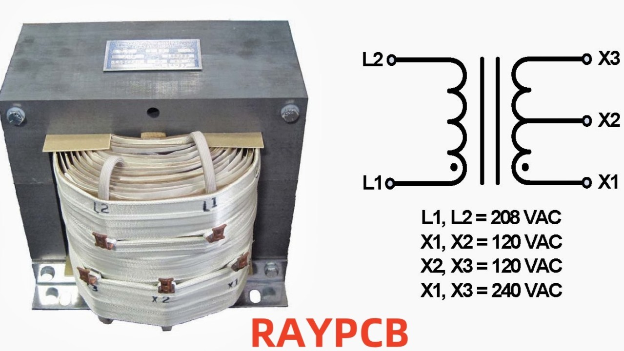
Center-Tapped Transformers: A Brief Introduction into Its Working and Applications
Center-tapped transformers are essential components in many electronic circuits, providing unique advantages in power supply and audio applications. This comprehensive guide explores their working principles, applications, and benefits.
Understanding Center-Tapped Transformers
Basic Structure
A center-tapped transformer differs from a standard transformer by having an additional connection point at the electrical center of either the primary or secondary winding, most commonly the secondary. This center tap effectively divides the winding into two equal portions.
Working Principle
The center tap creates two equal but opposite phases of voltage output, making it particularly useful for:
Components and Construction
Physical Components
Manufacturing Considerations
RAYMING PCB, a leading manufacturer in the electronics industry, specializes in creating PCB assemblies for center-tapped transformer applications. Their expertise includes:
Technical Specifications
Electrical Parameters
Voltage Relationships
Current Handling
Applications and Uses
Power Supply Applications
Full-Wave Rectification
Dual Voltage Supplies
Audio Applications
Push-Pull Amplifiers
Signal Processing
Design Considerations
PCB Layout Guidelines
When designing PCB layouts for center-tapped transformer circuits, RAYMING PCB recommends:
Component Selection
Core Material Selection
Winding Specifications
Performance Optimization
Efficiency Improvements
Loss Reduction
Thermal Management
Testing and Validation
Electrical Testing
Parameter Verification
Performance Testing
Installation and Mounting
PCB Assembly Guidelines
RAYMING PCB provides these key assembly recommendations:
Safety Considerations
Electrical Safety
Thermal Safety
Troubleshooting Guide
Common Issues
Electrical Problems
Mechanical Issues
Maintenance and Care
Preventive Maintenance
Lifetime Extension
Future Developments
Technology Trends
Emerging Applications
Cost Considerations
Manufacturing Costs
Operating Costs
Frequently Asked Questions
Q1: What is the main advantage of using a center-tapped transformer?
A: The primary advantage is its ability to provide two equal but opposite phases of voltage from a single winding, making it ideal for full-wave rectification and push-pull applications. This results in more efficient power conversion and better voltage regulation compared to non-center-tapped alternatives.
Q2: How does the center tap affect transformer efficiency?
A: The center tap typically has minimal impact on overall transformer efficiency. However, it provides better voltage utilization in full-wave rectification circuits, leading to improved system efficiency. The key is proper design and manufacturing, which is why working with experienced manufacturers like RAYMING PCB is crucial.
Q3: Can center-tapped transformers be used in high-frequency applications?
A: Yes, center-tapped transformers can be used in high-frequency applications, but special consideration must be given to core material selection, winding technique, and PCB layout. The design must account for parasitic effects that become more pronounced at higher frequencies.
Q4: What are the common failure modes of center-tapped transformers?
A: Common failure modes include voltage imbalance between taps, core saturation, winding failures due to overheating, and insulation breakdown. Regular maintenance and proper operating conditions can significantly reduce these risks.
Q5: How do I select the right center-tapped transformer for my application?
A: Selection criteria should include power requirements, frequency range, voltage ratios, current requirements, and environmental conditions. It's recommended to consult with experienced manufacturers like RAYMING PCB who can provide guidance based on your specific application needs.
Conclusion
Center-tapped transformers are versatile components that play a crucial role in many electronic applications. Understanding their working principles, applications, and maintenance requirements is essential for optimal implementation. Working with experienced manufacturers like RAYMING PCB ensures proper design, manufacturing, and implementation of these components in your electronic systems.